Testing Outdoor Pendants: a New Standard
By Product Development Engineer, Tom Keul
When innovating new products, the Visa Lighting engineering team always tries to follow our company and industry standards for quality and safety. However, before launching our new line of outdoor pendant lighting fixtures, it quickly became evident that little is known about product testing for catenary installations. Many variables come into play regarding the physical characteristics of products that are catenary mounted (on a cable strung between support structures), but there were no specific industry standards, no guidelines, and no regulations on which to base our designs.
So, we decided to branch out.
Visa Lighting’s new catenary mounted product lines are tested to the typical performance and safety standards one could expect of an outdoor luminaire: UL1598, IP65, etc.
Introducing the newest addition to our product testing, sought out for this environment specifically, ANSI C136.31: American National Standard for Roadway and Area Lighting Equipment – Luminaire Vibration (C136).
This testing is targeted towards roadway mounted luminaires that experience vibration from wind and traffic. The results from this test are used to determine mounting pole size, mounting bracket size, and materials used in the construction of products like your common city street lights.
While the same vibration conditions (wind and traffic) apply to outdoor catenary lighting, it doesn’t quite work the same. Street lighting poles are intended to be rigid, but the cable in catenary installations creates a semi-rigid structure. This affects how that same vibration actually impacts the luminaire itself.
Some definitions
Frequency is the rate at which something is repeated over a period of time. Frequency is often measured in this context as Hertz (cycles/second).
Resonant (natural) frequency is the oscillation rate at which a system will take a small input and amplify the strength. If you have a 1G input you should normally have a 1G output; at resonant frequencies the output could be 3, 5, or 20Gs. Many structures and objects/systems in nature resonate in the 0-30 Hz range.
Damping is the decrease in amplitude or bleeding of energy out of the desired system. This works to oppose resonance.
Amplitude is the physical displacement of a waveform measured from 0.
A “G” is an acceleration rate compared to that imposed by Earth’s gravitational force. An acceleration of 1.5Gs is similar to being on a planet that pulled you down toward it 50% more than Earth does naturally. Acceleration is not just due to gravity – it can also be calculated as a function of frequency and amplitude.
What does this all mean?
Whether it’s a pole or a catenary cable, all structures will react to wind loading in a similar manner, just like a wave. A good analogy is a guitar string. When a guitar string (pole or catenary mounting) is plucked (wind loaded) it vibrates at a specific frequency that is associated with how stiff the string is. If a pole is a stiff guitar string, a catenary cable is a much looser guitar string.
Catenary lighting doesn’t behave the same way as typical pole mounted lighting under wind load conditions. That makes the C136 test illegitimate. It all comes back to the cable as a semi-rigid structure. Aircraft cable acts more like a spring (a loose guitar string) than it does a rigid beam (an ultra-stiff guitar string). To further complicate things, each catenary-hung luminaire acts like a discrete mass hanging by the spring cable, which adds damping characteristics. Also, aircraft cable will stretch over time and sag, which further changes the natural frequency.
This all means that finding and holding a catenary structure at resonance is a very difficult, if not impossible, exercise. Since finding and holding resonance is one pass/fail criteria for C136, catenary systems will almost always fail.
We did two things to accommodate this issue:
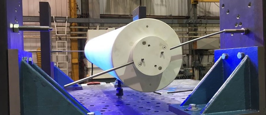
1. We mounted our products using a ¼”-diameter rod instead of a cable for testing. The more rigid our test stand, the more energy was transmitted to the fixture rather than absorbed by the test stand itself.
2. We did supplemental testing on cable structures outside the realm and restrictions of C136.
If the test is intended for rigid-mounted fixtures, the easiest and most logical way to get a pass/fail result is to rigid-mount the luminaire. Since we were no longer testing the cable construction, we performed additional stress testing so we could validate our mounting scheme and assumptions.
Why perform to this standard when it doesn’t apply to our fixtures?
Although C136 is intended for rigid-mounted luminaires, it provides valuable insights regarding outdoor environmental considerations and how products will or should react – regardless of their mounting method. Also, by securing something in place with a solid structure rather than a cable, we apply more energy to the product than would normally occur. It creates an exaggerated worst case condition, which adds a qualitative safety factor. This way, instead of just testing the mounting system, we also stress test the connections, the solder joints, the circuit boards, the adhesive joints, etc.
Also, the fixtures on the cable serve as damping masses in the system. Coupled with the fact that the cable stretches over time, it is extremely difficult for the fixture itself to obtain a resonance. This means that the structure as a whole is actually MORE stable and REDUCES the total vibrational load the system sees (including the impact on a luminaire). As soon as a resonant frequency at some amplitude is hit, the system destroys the resonance and prevents further amplification.
Therefore, if a product is tested to C136 and passes for rigid mounted applications, and if by default catenary mounting systems dampen environmental loading, then the product will withstand catenary applications for similar or longer durations than C136 is intending or testing to.
So why do we test to 3G? Why not 5, 6, or 342G?
C136 has two tables describing which minimum load conditions are required for testing. One is for “Normal Applications,” and the other is for “Bridge/Overpass Applications.” For most enclosure materials, the test accelerations are 1.5 and 3G, respectively. We chose to use 3G to cover more possible installation types.
We also chose not to target a higher value since there is no real theoretical limit. There is no such thing as indestructible when it comes to vibration testing; there will always be a frequency/amplitude combination that can utterly tear apart a product. So, we stuck with the requirements for the industry standard we had in front of us.
In brief, we used ANSI: C136 to test our new catenary-mount luminaires even though it is meant for pole/surface mounted product. We did this because a testing standard for catenary lighting fixtures does not exist, and because these test conditions greatly exaggerate the amount of strain a catenary-mounted fixture would ever have to endure.
Perhaps the future holds more specific industry regulations which will mimic the exact stress of a catenary installation. But until then, we know one thing for certain: our outdoor pendants have already passed.